


Roll-Fed XMFP10 Paper Cushion Machine: Following the Upright Supply Path
2026-10-25 11:01
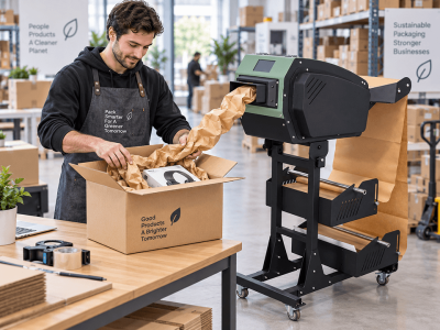
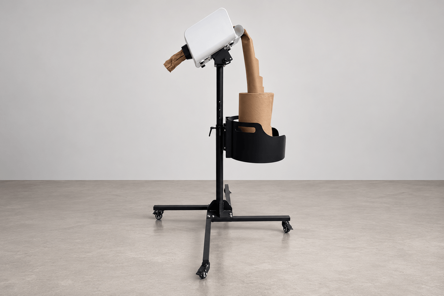
A roll-fed paper cushion machine includes more than a forming head. The incoming supply needs a defined support, a route into the equipment, and access for replenishment. Recycle Paking’s roll-feed XMFP10 photographs show a distinctive arrangement: an upright paper roll in a curved cradle beneath a tilted white head, all carried on a floor stand.
The official Paper Void Fill Machine With Kraft Roll Paper page identifies the equipment as XMFP10 in its specification table. Following the photographed paper path explains what this particular configuration adds to the machine order. It also helps a buyer describe the required assembly more precisely than requesting a paper cushion machine without specifying its supply arrangement.
The upright cradle defines the supply position
In the official configuration, the brown roll stands vertically inside a black curved cradle with handle cutouts. The cradle is mounted beside the central support post, below the forming head. This establishes a specific location for the incoming supply and makes the roll support part of the installed machine assembly.
The photographs show paper rising from the roll’s central area toward the back of the head. That visible arrangement differs from the familiar image of a horizontal roll carried on an axle. When describing this configuration, identify the upright cradle and the photographed draw path together. A generic reference to a roll holder would leave important details of the assembly unstated.
Follow the paper from storage to the forming head
The paper path has several visible sections. First comes the stored roll in the cradle. Above it, the drawn paper rises toward a curved inlet lip behind the white head. On the opposite side of the head, a short section of formed paper projects from the black outlet. These positions distinguish incoming supply from material ready for collection.
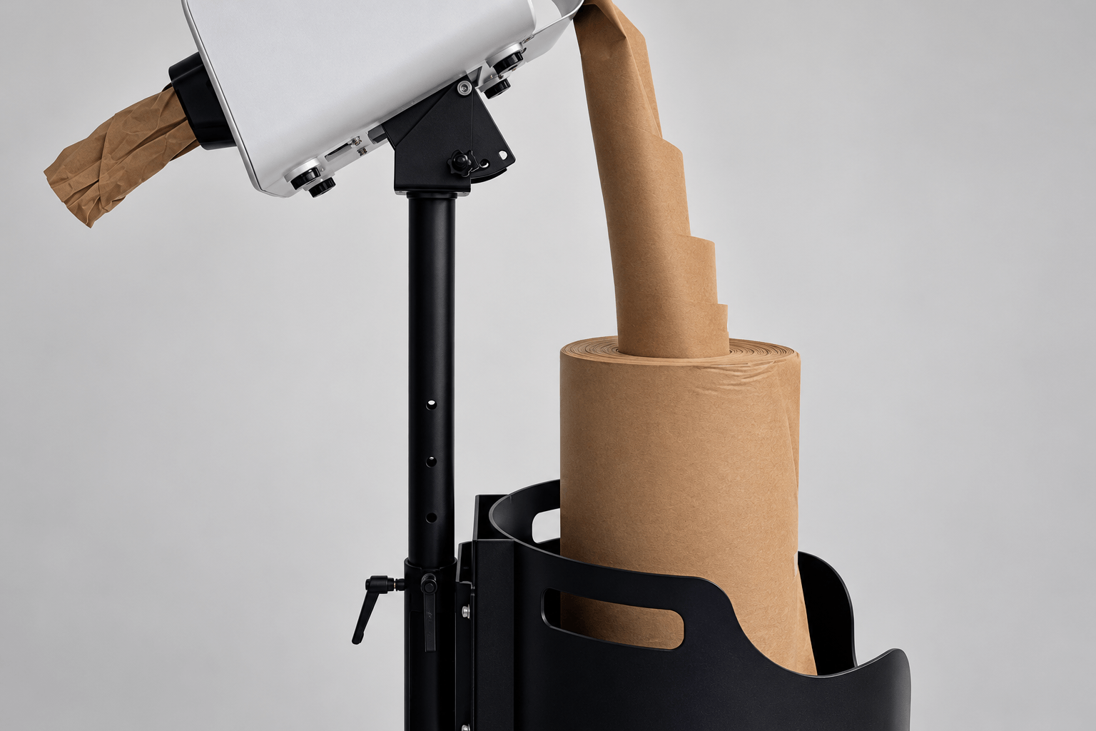
For a workstation plan, preserve room for that rising section as well as for the roll itself. Cartons and staging shelves should fit around the intended paper route. This keeps replenishment and output collection connected to the actual equipment layout, instead of treating the visible forming head as the machine’s entire working envelope.
The stand positions the head above the supply
The photographed floor stand places the head above the roll and supports the cradle on the same assembly. The side views also show the head inclined toward its collection side. Recycle Paking publishes adjustable height and angle for this machine configuration. Those features help relate the output position to the adjacent packing task.
For example, a machine placed beside a packing bench can present its outlet toward the area where formed paper will be collected. The supply remains below and behind the head in the photographed arrangement. Describe both positions when planning installation: the packer needs convenient access to output, while replenishment requires access to the cradle.
What remains common to the XMFP10 equipment discussion
| Published feature | Role in this configuration |
|---|---|
| XMFP10 model identification | Connects the roll-feed listing to the named machine |
| 100W power | Listed equipment power |
| 50 m/min paper speed | Published linear output figure |
| Single, automatic and pedal modes | Operating modes listed on the roll-feed product page |
| Adjustable height and angle | Positioning features for the head and outlet |
The main XMFP10 machine page also describes paper-pad forming with automatic and pedal operation. The control choice governs how output is requested, while the roll assembly governs where incoming paper is supported. Include both in the equipment discussion so the requested supply arrangement is clear alongside the preferred operating method.
The stated paper speed describes the conversion stage. A complete packing cycle also includes collecting a section and placing it around the goods. The upright roll arrangement is therefore best understood as a specific way to supply that conversion stage, rather than a separate promise about finished cartons per minute.
Use the head and outlet as the collection reference
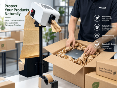
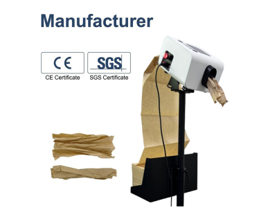
The front photograph shows the white head, its dark display, a column of five round control buttons, and the black outlet with formed kraft paper emerging. This is the operator-facing end of the photographed assembly. A useful machine demonstration can show that collection point together with the roll and rising infeed, making the full process visible.
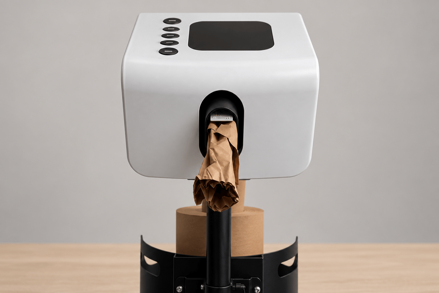
At a repeated carton-packing position, the operator can collect formed paper at the outlet and place it in the required spaces. During replenishment, attention returns to the lower supply cradle. Keeping those two activities distinct helps explain why access around the complete assembly matters, even though the forming head is the most noticeable component.
Specify the roll-feed assembly in the machine inquiry
Recycle Paking’s Paper Cushion Solution range provides the wider equipment context. For a quotation for this XMFP10 arrangement, include the official roll-feed product link or photograph, intended paper specification, destination country, preferred operating mode, and the outlet position required beside your bench. Ask for the pictured upright roll support and floor-stand configuration so the equipment request describes the complete machine.
Related News
Read More >-
![Kraft Cushion Paper: A Practical and Sustainable Solution for Protective Packaging]()
Kraft Cushion Paper: A Practical and Sustainable Solution for Protective Packaging
Discover how kraft cushion paper provides sustainable protection for e-commerce, warehouses, fragile products and industrial packaging while reducing plastic void fill.
-
![Paper Cushion Machine: A Smarter and More Sustainable Solution for Protective Packaging]()
Paper Cushion Machine: A Smarter and More Sustainable Solution for Protective Packaging
As businesses around the world look for more sustainable ways to protect products during shipping, paper-based protective packaging is becoming an increasingly popular alternative to traditional plastic materials. A paper cushion machine is designed to convert kraft paper into strong, flexible cushioning material that can be used for void filling, wrapping, blocking and bracing inside cartons. It provides an efficient packaging solution for e-commerce companies, warehouses, manufacturers, logistics centers and retail fulfillment operations. For companies looking to reduce plastic packaging while maintaining reliable product protection, paper cushioning offers a practical balance between performance, efficiency and sustainability.
-
![Produce High-Quality Cushion Paper for Cosmetic Products with Paper Cushion Machine]()
Produce High-Quality Cushion Paper for Cosmetic Products with Paper Cushion Machine
The beauty and cosmetic industry demands exquisite, safe, and eco-friendly packaging solutions to protect high-value products such as liquid serums, cream foundations, facial essences, and skincare concentrates. These cosmetic items feature delicate glass bottles, fragile plastic containers, precise internal formulas, and sensitive textures, making them highly prone to damage from extrusion, collision, vibration, and temperature friction during transportation, storage, and logistics turnover. To solve these packaging protection pain points, adopting a professional paper cushion machine to produce customized cushion paper has become a cost-effective, sustainable, and high-efficiency packaging choice for cosmetic brands of all sizes. Compared with traditional bubble wrap, foam inserts, plastic fillers, and kraft paper scraps, machine-made cushion paper provides tailored, shock-absorbent, and dust-free packaging protection that perfectly matches the packaging standards of high-end cosmetic products.
-
![Sustainable Shipping Redefined: The Power of Paper Cushion Systems]()
Sustainable Shipping Redefined: The Power of Paper Cushion Systems
Revolutionizing Protective Packaging: Why Your Business Needs a Paper Cushion Machine In an era where sustainability meets high-velocity logistics, the choice of packaging material is no longer just about protection—it’s about brand values and operational efficiency. As global regulations tighten around single-use plastics, the Paper Cushion Machine has emerged as the gold standard for eco-conscious enterprises.
-
![Paper Bubble: The Plastic-Free Revolution in Protective Packaging]()
Paper Bubble: The Plastic-Free Revolution in Protective Packaging
Paper Bubble: The Plastic-Free Revolution in Protective Packaging In the modern logistics landscape, the "unboxing experience" is just as important as the product itself. As global restrictions on single-use plastics tighten, brands are seeking sustainable alternatives to traditional plastic bubble wrap. Enter **Paper Bubble**—an innovative, biodegradable cushioning solution that offers the same protection as plastic, but with a premium, eco-friendly finish. ## What is Paper Bubble? Paper Bubble is a unique cushioning material made from renewable Kraft paper. Unlike Honeycomb paper (which requires stretching), Paper Bubble is created by a specialized machine that embosses deep indentations—or "bubbles"—into the paper surface. These air-filled dimples provide robust shock absorption and resistance against impact, all without using a single gram of plastic. ## Key Applications: Versatility Meets Protection Paper Bubble is designed for small-to-medium-sized products that require delicate handling. Here is how different industries are applying this technology: ### 1\. Cosmetics and Beauty For high-end skincare, perfumes, and glass makeup bottles, presentation is key. Paper Bubble offers a clean, organic texture that enhances the perceived value of the product. * **Application:** Wrapping perfume bottles, padding gift boxes, and separating glass jars. * **Benefit:** It replaces messy plastic wrap with a neat, boutique-style presentation. ### 2\. Ceramics and Home Goods Fragile items like dinnerware, porcelain vases, and glass ornaments are prone to breakage during transit. The embossed structure of Paper Bubble acts as a shock absorber. * **Application:** Interleaving between plates (as seen in the main image), wrapping ceramic bowls, and protecting glassware handles. * **Benefit:** Prevents surface scratches and absorbs impact energy from drops. ### 3\. Electronics and Gadgets Plastic packaging can generate static electricity, which is harmful to sensitive electronic components. Kraft paper is naturally anti-static. * **Application:** Wrapping hard drives, handheld devices, and accessories. * **Benefit:** Provides safe cushioning while minimizing static risks. ### 4\. E-Commerce Fulfillment (Void Fill) Paper bubble isn't just for wrapping; it is flexible enough to be bunched up and used as void fill to stop items from shifting inside the carton. * **Application:** Filling gaps in shipping boxes for general retail goods. * **Benefit:** Lightweight nature keeps shipping costs low. ## Why Choose Paper Bubble Over Plastic? * **100% Curbside Recyclable:** Your customers can toss the packaging directly into their paper recycling bin. No separation required. * **Storage Efficiency:** The raw material comes in compact, fan-folded stacks (unlike massive rolls of pre-inflated plastic bubbles), saving up to 80% of your warehouse space. * **Brand Image:** Using paper packaging signals to your customers that your company is committed to environmental sustainability. ## Conclusion The transition to eco-friendly packaging is no longer optional; it is a competitive advantage. Paper Bubble provides the perfect balance of engineering protection and environmental responsibility. **Ready to eliminate plastic from your shipping process? Contact us today to learn more about our Paper Bubble machines and consumables.**
-
![Honeycomb Paper: The Future of Lightweight and Sustainable Materials]()
Honeycomb Paper: The Future of Lightweight and Sustainable Materials
In a world increasingly focused on sustainability and efficiency, innovative materials are transforming industries. Honeycomb paper, a groundbreaking material known for its unique structure and exceptional properties, is emerging as a game-changer across multiple sectors.
-
![Revolutionizing Recycling: The Cardboard Shredder Machine]()
Revolutionizing Recycling: The Cardboard Shredder Machine
A cardboard shredder machine is a robust industrial device specifically engineered to shred cardboard into smaller pieces or strips. These machines are equipped with powerful motors and sharp blades capable of processing large volumes of cardboard quickly and efficiently. They come in various sizes and capacities, catering to different needs, from small businesses to large-scale recycling operations.
-
![C Folded Void Fill Paper]()
C Folded Void Fill Paper
When packing the product in corrugated boxes, care must be taken to ensure that the product remains intact and does not move during transport. For this, a Void Fill packaging system is used, through which the empty spaces are filled with Void Fill paper, which provides extreme protection and padding of the product, keeping it safe throughout the delivery process. C-fold paper is commonly used to fill empty spaces in packaging boxes. It is also known as continuous paper or C-fold paper. Made from 100% biodegradable Kraft paper, it's a great choice for an eco-friendly packaging solution. It is an alternative to air cushions, bubble wrap and foam due to its durability and high protection; it has largely replaced other packaging fillers such as air cushions, bubble wrap or foam. It also has a very good compression property that can withstand shocks during transportation without damaging the product.